Options
Options Panel in the bottom left of the viewport
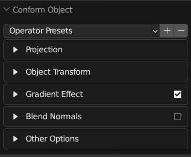
The options panel with each section collapsed.
Operator Presets
You can add or remove preset configurations from the tool here by pressing the + or - keys, or reset the tool to its default parameters.
Projection
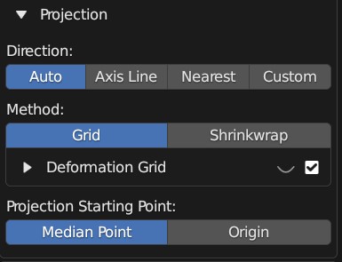
The expanded Projection Panel
The following controls the parameters of how the source object is projected onto the Target Object:
Direction
A source object having its projection direction changed by custom mode (Grid mode visibility is turned on). When the direction line hits the Target Object, the Source Object begins to conform.
The different Direction modes control how the direction line is chosen when projecting the Source Object. You may wish to enable Grid visibility to see the different modes working:
Auto: This mode will first try to project the Source Object onto the Target Object using the negative Z direction as usual, and if that fails, it will instead project onto the closest point on the Target Object.
Axis Line: This will project a line from the middle of the Source Object in the local X, Y or Z direction with the object’s rotation taken into account. By default, the projection is in the local -Z direction. If the line misses, a warning message will be displayed.
Nearest: This will project a line from the middle of the Source Object to the closest point on the Target Object. You may need to use the Transform Orientation section to adjust the position of the object whilst it is being projected.
Custom: Specify a X/Y/Z rotation for the projection line.
Method
This is the method used to deform the Source Object. Choose between Grid Mode or Shrinkwrap Mode:
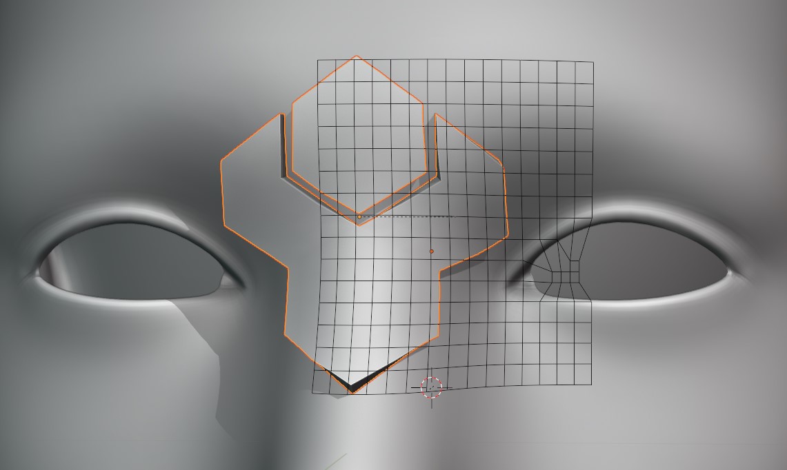
Grid Mode: This mode is described here, and creates a projection grid object which is attached to the source object to create the deformation. The grid object is a regular blender object, parented to the source object.
Visibility: The grid object is hidden by default, but can be revealed by clicking the eye icon next to the Deformation Grid section:
Switching on and off Grid visibility.
Tip
If you wish to hide the Grid again after the Conform Object operation is performed and the panel is gone, expand the Source Object in the Outline View to find the grid object:
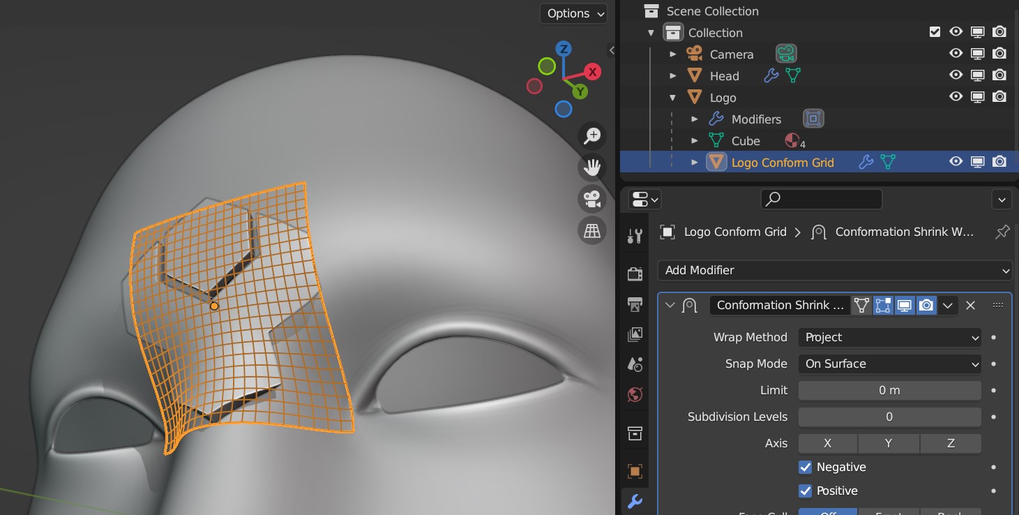
Selecting the Grid on the Outline View.
Then make sure you have the Disable In Viewports flag ticked in the filters section of the Outline view:
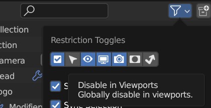
Selecting the Disable in Viewports flag.
You can then hide the grid object completely again by clicking this flag next to the object in the Outliner view:
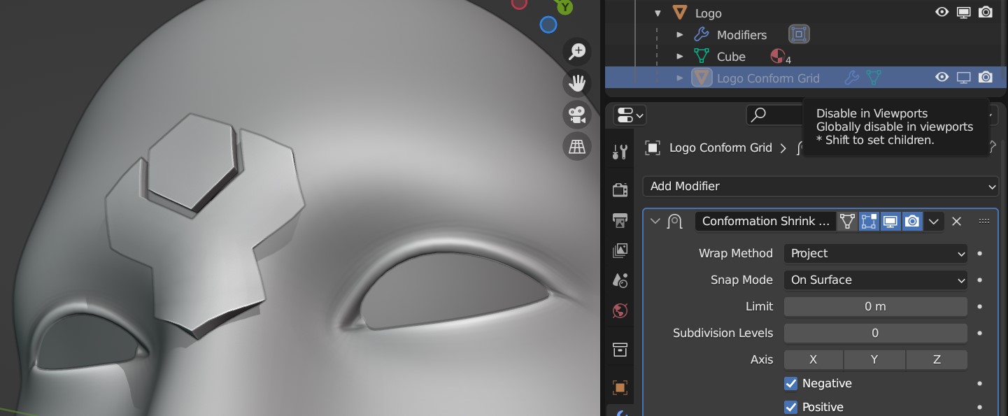
The grid is hidden again.
Grid options: By expanding the Deformation Grid section, you can change the default parameters of the grid:
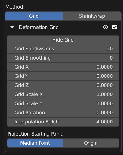
Expanded Grid Options section.
Show/Hide Grid: By default, the deformation grid is hidden but it can be displayed if you wish to configure it. This is the same setting as the Eye icon in the Deformation Grid section header.
The deformation grid is revealed!
Grid Smoothing
Applying a Subdivision Surface modifier to the grid for smoothing: Levels 0, 1 and 2 are applied here.
This adds a Subdivision Surface modifier to the grid. This helps smooth the deformation grid over jagged surfaces.
Grid Subdivisions
Subdividing the grid increases the resolution of the deformation.
Not to be confused with grid smoothing, this is the number of vertices in the grid. If you are deforming over particularly smoothed or high resolution meshes, increasing this number can be useful.
Grid X/Y
Grid moved in X direction.
Move the grid’s X/Y position.
Grid Scale X/Y
Scale the influence of the grid.
Scale the grid in the X/Y direction.
Grid Rotation
Grid rotated on surface.
Rotate the grid over the surface.
Interpolation Falloff: Used on the Surface Deform Modifier for the grid. From the Blender documentation: “How much a vertex bound to one face of the target will be affected by the surrounding faces (this setting is unavailable after binding).”
Projection Starting Point
This parameter controls where the beginning of the projection line from the Source Object to the Target Object should be:
Median Point: By default, the start of the projection line will be from the middle point of the Source Object’s geometry.
Origin: Alternatively, you can make the projection line start from the Source Object’s origin point in the 3D scene.
Object Transform
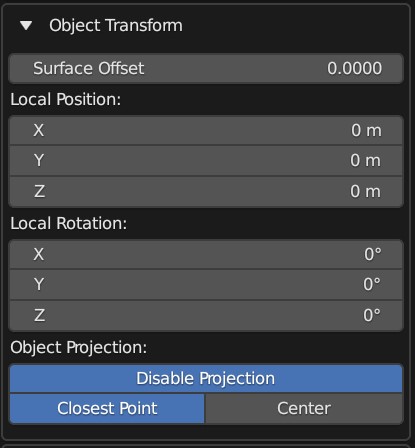
The expanded Object Transform Panel
These parameters control how the Source Object is positioned onto the Target Object during the Conform Object operation.
Surface Offset
This parameter controls how far away the Source Object is offset from the Target Object’s surface.
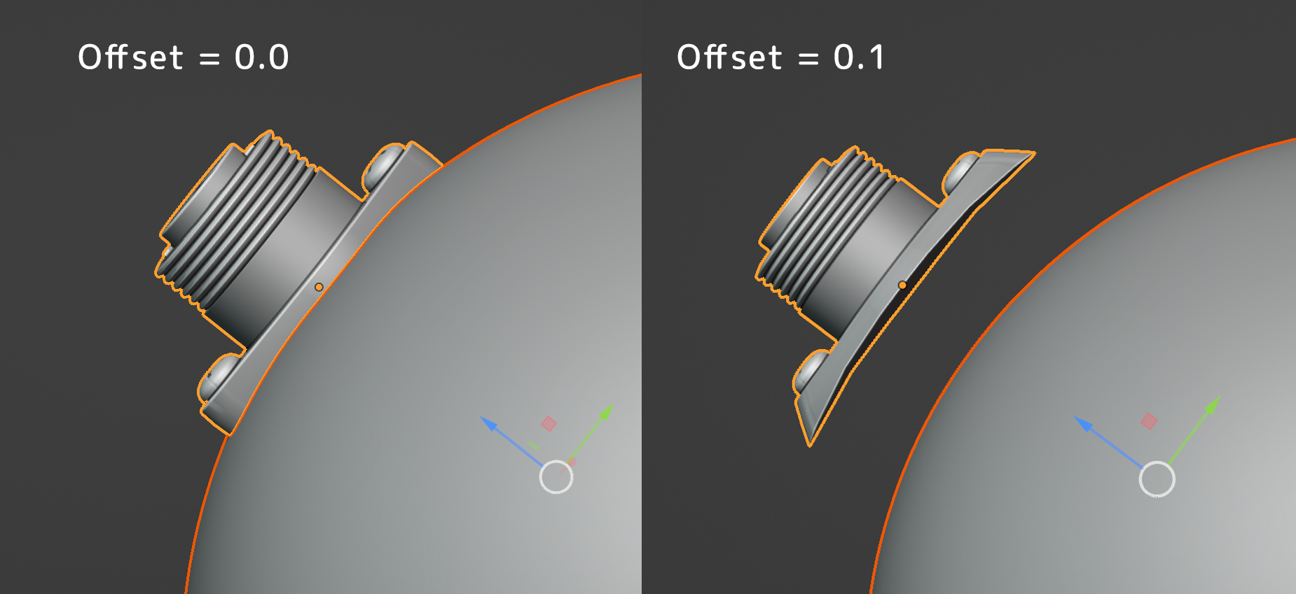
Source Object being offset.
Local Position
Once the Source Object has been projected, this controls the relative position of the Source Object.
Source Object being repositioned.
Local Rotation
This controls the rotation of the Source Object once it has been projected. This is useful for adjusting the orientation of the object after the initial projection.
Source Object being rotated on the surface.
Object Projection
The Source Object can either be projected onto the surface using its closest part or its center.
Here you can choose which point on the Source Object is used to position it on top of the Target Object’s surface.
Disable Projection: Disable projection entirely. This will stop the Source Object from being moved, which can be useful when trying to manually place the Source Object using the Local Position and Rotation parameters.
Closest Point: By default the closest point on the Source Object to the Target Object will be used to position the Source Object on top of the Target Object’s surface.
Center: The center of the Source Object’s geometry will be used to place it on the surface of the Target Object, so the Source Object will be ‘inside’ the Target Object surface.
Gradient Effect
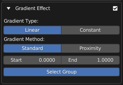
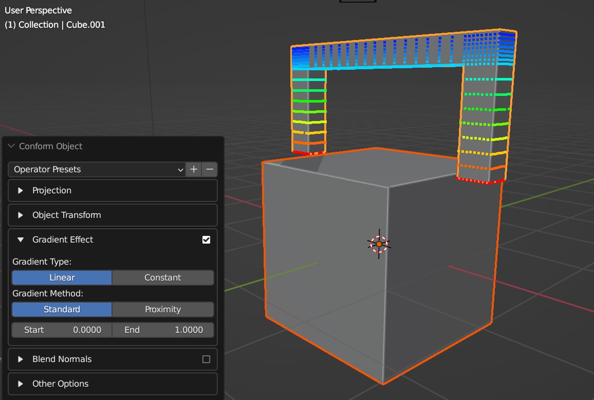
The expanded Gradient Effect Panel.
The Gradient Effect creates a vertex group which automatically adds weighted values to the vertices at the bottom of the Source Object so the effect is less exaggerated at the top:
The Gradient Effect allows you to control where the Source Object is deformed. In this case, we do not want the threads of the screws to be affected, so we reduce the End parameter so that the effect finishes towards the bottom of the object.
Tip
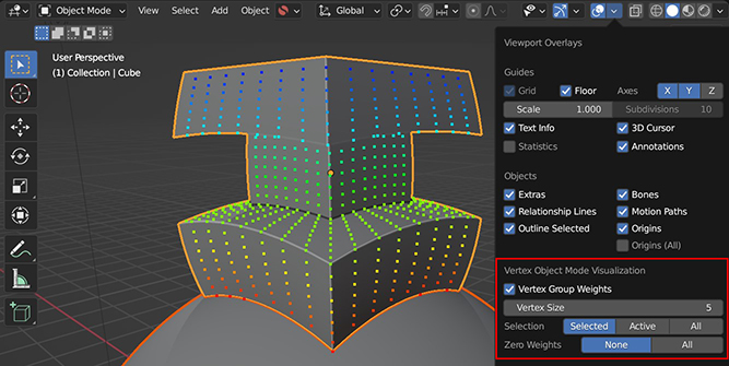
View the Vertex Groups used by the Gradient Effect whilst using the add-on with this additional feature.
Gradient Type
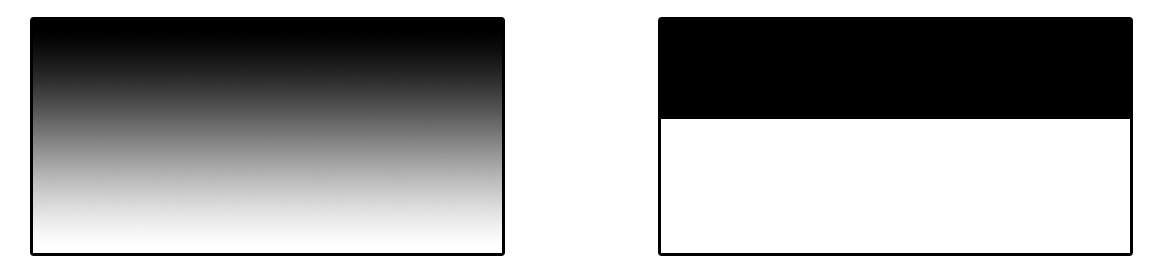
The type of gradient to apply: Linear (Left), or Constant (Right)
This setting determines which style of gradient effect to apply:
Linear: this will create a gradually decreasing effect between two values.
Constant: this will create a hard falloff from 1 to 0.
Gradient Method
This controls the method used to apply Vertex Group weights in the Gradient Effect:
Standard: By default the weighting will be strongest at the closest points on the Source Object to the Target Object.:
Proximity: The weighting will be strongest for vertices that are nearest the Target Object surface. This is useful when attempted to set up objects that ‘wrap’ more to the Target Object when using Shrinkwrap Mode.
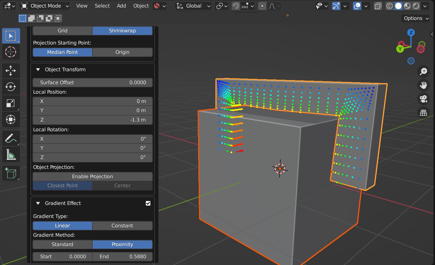
Here the proximity gradient effect is applied, where projection has been disabled and instead the object has been positioned using local controls. Instead of Grid Mode, Shrinkwrap Mode is being used instead. This helps wrap objects more, but may need adjusting manually after the Conform Object operation is performed.
Start/End

Start/End controls
This controls when the gradient effect of the vertices starts and ends.
A value of 0.0 is at the bottom of the object, and a value of 1.0 is at the top.
Lowering the value of the end below 1.0 will stop the deformation towards the bottom of the object, and higher values will extend the weight beyond the top of the object. Increasing the start value will start the weighting higher up the object.
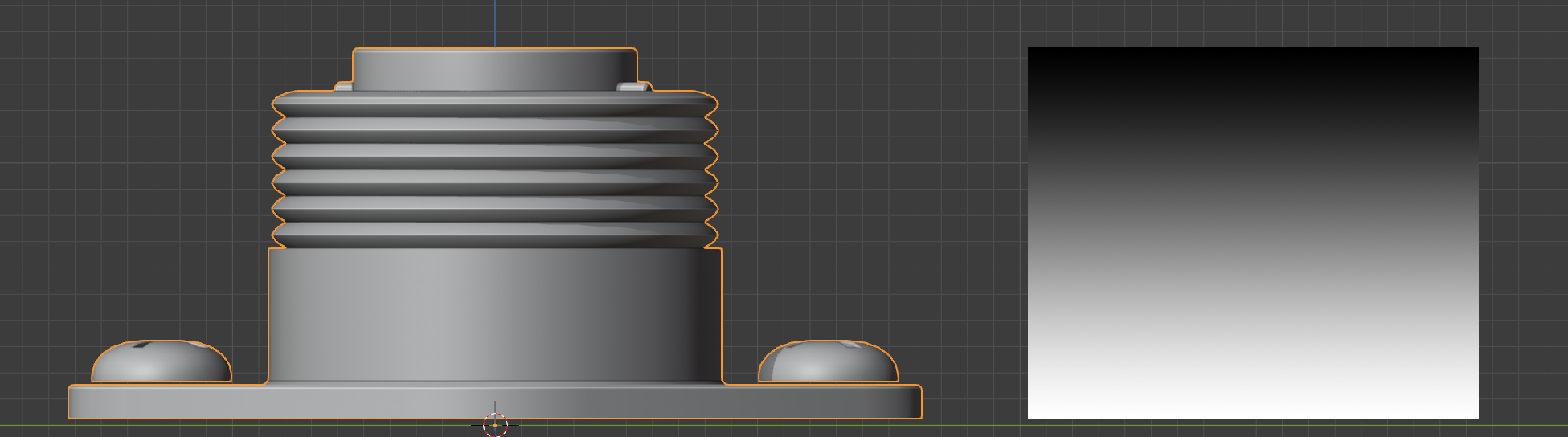
The default vertex group weighting, where the effect is gradually reduced towards the top (Start=0.0, End=1.0)
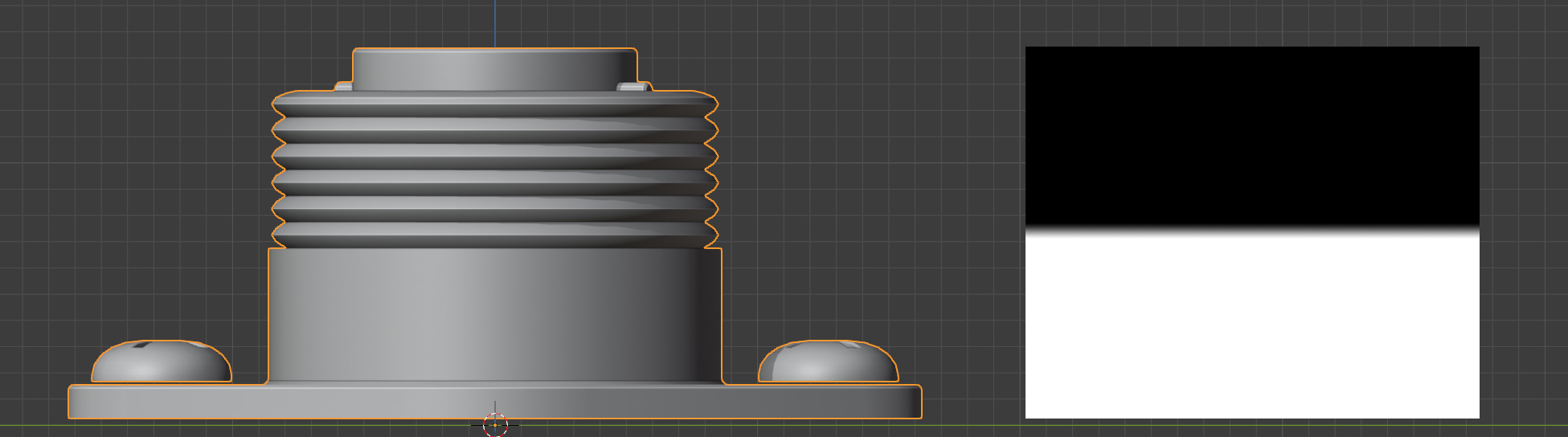
Vertex group weighting where the start point has been increased so the effect covers the lower part of the object entirely (Start=0.45, End=0.55)
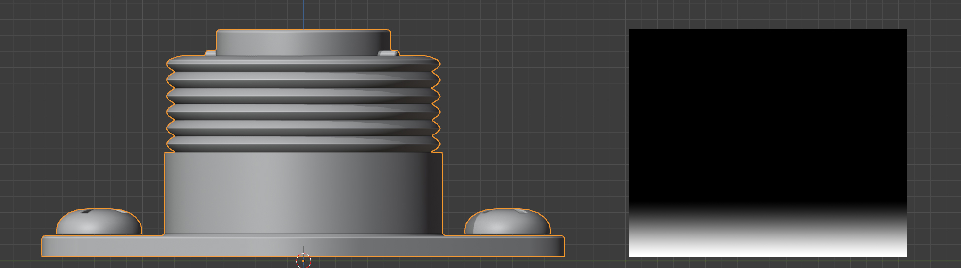
A lower vertex group weighting, where the effect is gradually reduced further towards the bottom (Start=0.0, End=0.1)
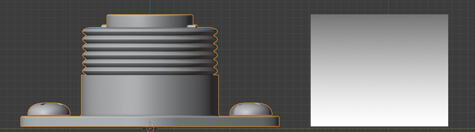
A higher vertex group weighting, where the effect is gradually reduced beyond the top of the object (Start=0.0, End=2.0)
Blend Normals
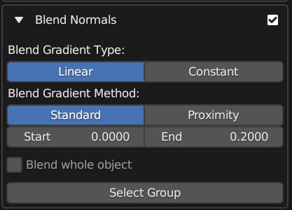
The expanded Blend Normals Panel.
This will blend the normals of the source object with the target object, creating a smoother transition between the two object surfaces:
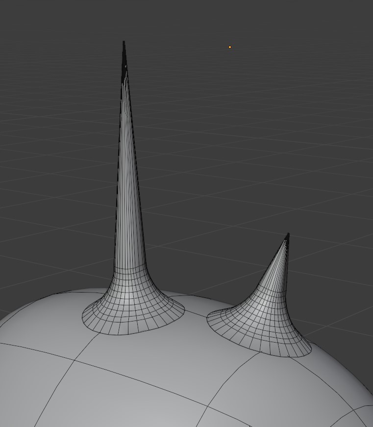
Some simple ‘horns’ applied using the add-on. They are all separate objects.
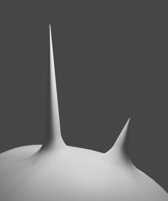
Here the normals of the same ‘horn’ objects are blended with the normals of the head. They remain separate objects.
This effect is achieved by using a Data Transfer Modifier on the Source Object, and uses the same Blender Vertex Group weighting to control the effect in the same way as the Gradient Effect above.
Gradient Type (Blend Normals)
As with the Gradient Type controls for the Gradient Effect, this controls which face normals are affected.
Gradient Method (Blend Normals)
As with the Gradient Method controls for the Gradient Effect, this controls which face normals are affected.
Start/End (Blend Normals)
As with the Start/End controls for the Gradient Effect, this controls which face normals are affected.
Blend Whole Object
This will blend all of the object’s normals regardless of the gradient effect.
Other Options
Add Simple Subdivisions
This adds a Subdivision Surface modifier to the source object, set to ‘simple’, in case you wish to quickly subdivide the mesh when conforming the object.
Subdivisions: The number of subdivisions to use in the modifier.
Collapse Modifiers
This will collapse the existing modifiers on the source object if they are interfering with the conform effect.
Deform Modifier Position
This will change the position of the deformation modifier (Either Surface Deformation of ShrinkWrap) on the source object:
Start: At the start of the modifier stack.
Before: This will place the modifier just before a specified modifier. Selecting the option will allow you to specify which modifier.
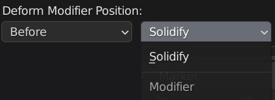
End: At the start of the modifier stack.
Parent Source Object to Target Object
Assign the Target Object as the parent of the Source Object.
Warning
Parenting the Target Object cannot be automatically undone by the add-on